
Série GM.SI
Les systèmes d’orientation à rayons X de la série GM.SI sont des unités de production robustes, spécialement conçues pour la détermination de la position du flat ou du notch sur tous types de monocristaux, des plus petites aux plus grandes dimensions.
Tous les types de monocristaux peuvent être traités, pour des applications telles que :
-
les semi-conducteurs
-
l’optoélectronique
-
l’optique
-
et autres applications industrielles et scientifiques
Procédés d’orientation
-
Flat & notch sur lingots « as grown » (bruts de croissance)
-
Flat & notch sur lingots rectifiés (cylindriques)
Mesures d’orientation
-
Flat lingot
-
Notch lingot
-
Axe de germe (graines rondes ou carrées, avec support optionnel)
-
Face wafer
-
Flat wafer (support optionnel)
Performances
-
Détection RX : ± 0,01°
-
Procédé d’orientation : ± 0,03° à ± 0,05°
(selon configuration et type de cristal) -
Mesures : ± 0,01° à ± 0,03°

Configurations
Les systèmes d’orientation à rayons X GM.SI-…-R sont des modèles spécifiques de notre série GM.SI, conçus pour fonctionner en association avec des équipements de rectification où le lingot est maintenu entre pointes, et où la broche de la rectifieuse est équipée d’un système de contrôle et d’affichage de rotation.
Comme l’ensemble des modèles de la série GM.SI, les versions GM.SI-…-R sont disponibles :
-
en unité simple station
-
ou en configuration mixte double station
Ces systèmes peuvent être combinés avec un poste de travail de la série GM ou GM.WS.
Goniomètre
Un ensemble goniométrique extrêmement robuste supporte l’ensemble du mécanisme de manipulation du lingot.
L’arbre du goniomètre intègre un support d’échantillon servant de plan de référence pour :
-
la calibration simplifiée de l’équipement
-
la mesure d’orientation des wafers
-
le montage de supports optionnels
Un rouleau de référence, dont l’arête se situe dans le même plan que le support, est monté directement sur l’arbre.
Plage de rotation goniomètre / détecteur : < 0° à environ 100°
Capacités
Les modèles GM.SI sont disponibles en plusieurs capacités, configurées selon les exigences de l’utilisateur.
Ils couvrent une large gamme d’applications, pour des diamètres allant de 2 pouces jusqu’à 200 mm, et des longueurs jusqu’à 800 mm.
Un modèle dédié est disponible pour des lingots de 300 mm de diamètre.
(Documentation spécifique sur demande)
Lecture angulaire
-
Affichage numérique de l’angle en degrés décimaux (0,01°), en degrés / minutes / secondes (en option), ou via un PC
-
Remise à zéro possible à toute position
-
Affichage alterné de la valeur angulaire absolue ou relative
-
Recalibration automatique au démarrage ou à tout moment
Sécurités et protections
L’équipement a été conçu pour offrir à la fois une protection maximale et une utilisation simple et fiable.
-
Obturateur rotatif électromagnétique commandé par une pédale non auto-maintenue
-
Interverrouillage de l’obturateur activé par le lingot en position de mesure
-
Voyants vert / rouge indiquant l’état de l’obturateur
-
Voyant « X-ray ON » avec arrêt automatique de l’équipement en cas de défaillance du voyant
-
Blindages et écrans empêchant toute exposition aux rayonnements directs ou diffusés
Générateur de rayons X
-
Tension de sortie : 30 kV – DC
-
Courant maximal : 30 mA
-
Tube à rayons X : cible cuivre, refroidissement par eau
-
Foyer apparent : foyer linéaire fin
-
Alimentation secteur : 220 V / 50–60 Hz, monophasé, 10 A
-
Alimentation en eau : 2,5 bar – débit 3,5 l/min
Unité de détection
Compteur proportionnel relié à un intégrateur spécifique avec amplificateur de pic, assurant une haute précision de détection.
La tension est réglable de 1000 à 1850 V.
Le voltmètre et le potentiomètre de réglage sont situés dans le coffret, côté opérateur.
La méthode la plus simple et la plus précise pour réaliser un flat ou un notch sur un lingot à l’orientation correcte consiste à utiliser le même système de maintien et de transfert d’orientation du lingot à la fois sur le goniomètre à rayons X et sur la rectifieuse flat/notch.
Les meilleurs résultats sont obtenus lorsque l’orientation déterminée sur le goniomètre peut être transférée à la rectifieuse simplement en réglant l’angle de rotation de la broche à une valeur donnée.
Cela est possible lorsque le goniomètre est équipé d’un affichage angulaire de la rotation du lingot et que la rectifieuse dispose d’un affichage angulaire de la rotation de la broche.
Système de maintien du lingot
Le lingot (équipé de deux pièces de centrage en acier) est maintenu entre deux centres à billes.
Le mouvement vertical du centre supérieur, monté sur une colonne rigide, est commandé pneumatiquement par des pédales, permettant de garder les mains libres.
L’ensemble est monté sur une table coulissante à commande pneumatique qui amène et maintient le lingot en contact avec le rouleau de référence, indépendamment du diamètre et de la forme du lingot (y compris lingots bruts de croissance).
Le faisceau se focalise au point de contact entre le lingot et le rouleau.
Rotation du lingot
L’ensemble bille-centre supérieur fait partie d’un cylindre rotatif intégrant également une goupille de référence.
Cette goupille est montée sur ressort.
L’angle de rotation du cylindre est affiché numériquement, de la même manière que la rotation du goniomètre.
Un système pneumatique de réglage fin et de freinage permet un contrôle précis de la rotation du lingot à toute position.
Procédé d’orientation du lingot
-
Fixer une pièce de centrage avec rainure à l’extrémité supérieure du lingot, et une pièce de centrage sans rainure à l’extrémité inférieure.
-
Placer le lingot entre les centres à billes du goniomètre, la goupille de référence de l’ensemble supérieur s’engageant dans la rainure de la pièce de centrage.
-
Procéder à l’orientation du lingot en le faisant pivoter jusqu’à l’obtention d’un pic de réflexion.
Utiliser le réglage fin de rotation pour obtenir une orientation précise. -
Noter la valeur affichée sur l’indicateur de rotation du lingot.
-
Placer le lingot sur la rectifieuse, la goupille d’indexation engagée dans la rainure de la pièce.
-
Après rectification du diamètre extérieur (OD) du lingot, faire tourner la broche de la rectifieuse jusqu’à ce que son affichage de rotation indique la même valeur que celle précédemment relevée.
-
Procéder ensuite à la rectification du flat ou du notch, puis au flat secondaire si nécessaire.


Ensemble rotatif supérieur avec codeur angulaire, centre à bille, goupille de verrouillage et réglage fin de rotation.

A – Goniomètre GM.SI-…-R
B – Rectifieuse équipée d’un système de maintien compatible et d’un affichage de l’angle de rotation
1 – Affichage de l’angle du goniomètre
2 – Affichage de l’angle de rotation du lingot
3 – Affichage de l’angle de rotation de la broche de la rectifieuse
4 – Pièce de centrage inférieure du lingot
5 – Pièce de centrage supérieure du lingot
Mesures d’orientation
Flat & Notch du lingot
-
Après rectification, le lingot est replacé sur le goniomètre et le dispositif de contrôle du flat ou du notch est mis en contact et maintenu contre le flat ou le notch du lingot
-
Le bouton de réglage fin du goniomètre est tourné jusqu’à l’obtention d’un pic de réflexion. Le système d’affichage angulaire du goniomètre indique directement l’erreur de rectification
Flat wafer
-
Un support dédié, facilement adaptable, est disponible.
Il peut être installé et retiré sans nécessiter de réinitialisation ou de recalibration de l’équipement.
(Voir illustration ci-dessous)
Axe de germe (Seed axis)
-
Un support spécifique est également disponible, se montant selon le même principe que décrit précédemment.
(Voir illustration ci-dessous)

Des pièces de centrage pour lingots de différentes dimensions (diamètre et longueur) peuvent être fournies afin de s’adapter aux configurations spécifiques de rectifieuses.
Des accessoires pour rectifieuse (centres à billes et ensemble goupille de verrouillage) peuvent également être fournis sur demande.
(Voir illustration à droite)
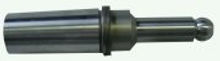
Centre à bille avec cône Morse pour rectifieuse.
L’ensemble goupille de verrouillage se monte sur la partie cylindrique.
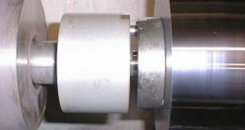
Rectifieuse équipée d’un centre à bille et d’un ensemble goupille de verrouillage.

Accessoire pour mesure d’orientation du flat wafer

Accessoire porte-germe (seed holder)
Delta Technologies améliore en permanence ses produits.
Les équipements peuvent différer des caractéristiques mentionnées dans le présent document non contractuel.